
2026 / FUSION ADD-IN
Aluminum Extrusions
From aluminum frame design to a MISUMI order list.
MISUMI aluminum frame design add-in
Aluminum Extrusions
Aluminum Extrusions is an Autodesk Fusion add-in that assigns MISUMI aluminum extrusions (5 / 6 / 8 series) to sketch lines, builds frames and trims joints automatically. Members get MISUMI order codes (e.g. HFS5-2020-500) automatically, and brackets and nuts are placed as real geometry. When the design is done, the order list is ready.
The challenge
Designing equipment with aluminum frames usually means placing frames one by one, transcribing lengths and part numbers into a spreadsheet, and creating the purchase order. Every design change meant recounting lengths and re-picking brackets and nuts — time-consuming and error-prone.
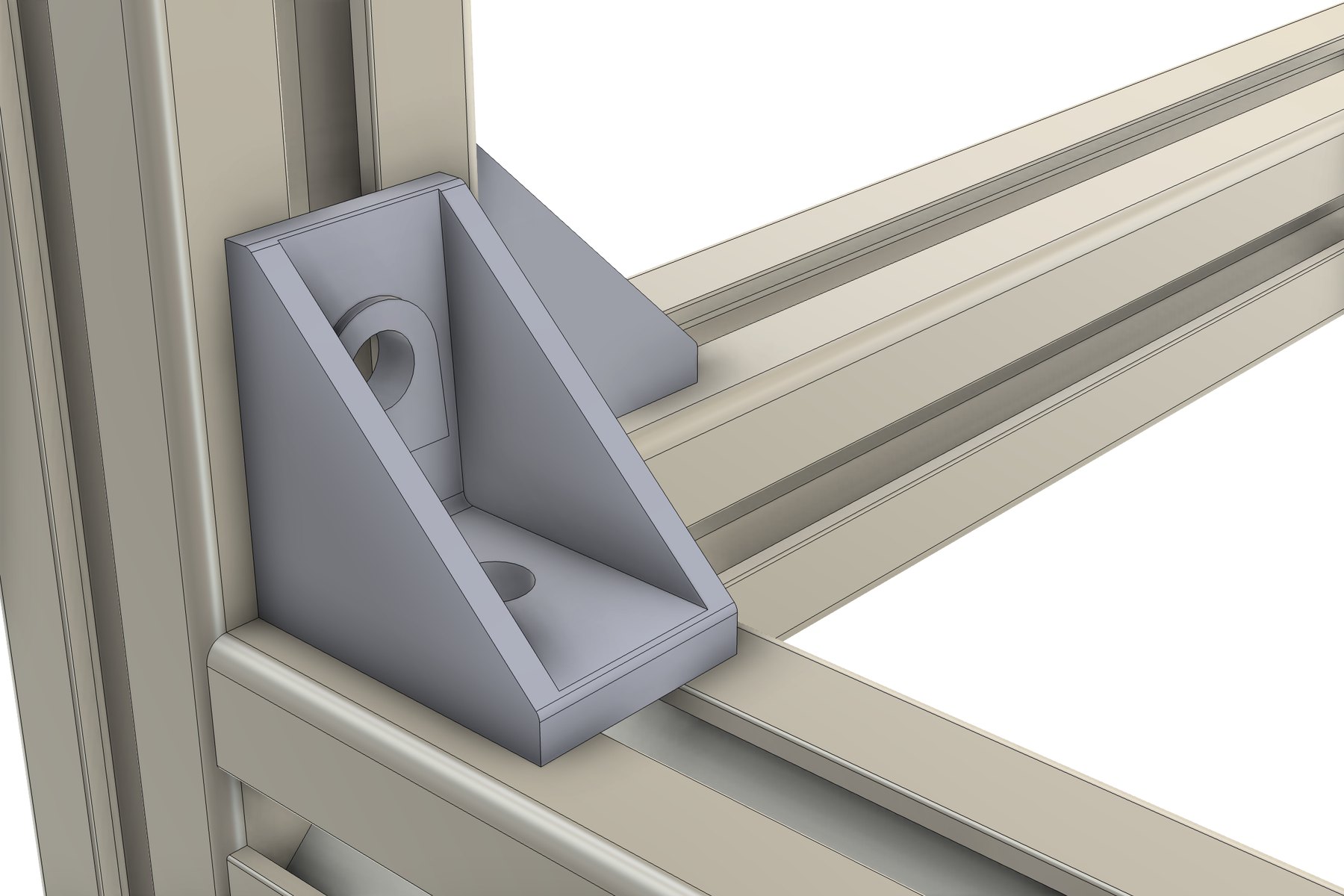
Aluminum Extrusions features
Supports MISUMI 5 / 6 / 8 series
139 part numbers including HFS, HFSF, HFST, HFSH, HFSL, GFS, EFS, CAF and NFS families. Profiles are built from MISUMI CAD data, with cross-section area and second moment of area checked against catalog values.
Order codes become part numbers
Each member component’s part number is set to the order code (with length), so it appears directly in Fusion’s BOM and drawing parts lists.
Joint trimming and placement rules
Supports butt, miter and T-joints. With Inside placement, frames are kept inside the outline regardless of line direction.
Real-geometry brackets and nuts
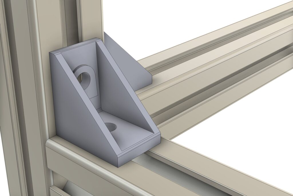
HBLFSN brackets and HNTT / HNTF / HNTU / HNTP nuts are placed from MISUMI STEP data. Hardware follows when you change the frame.
Lightweight display modes
Switch between Detailed (slots and hollows), Outline Only and Envelope. Large equipment frames stay light, and mass uses catalog values in every mode.
Cut list with order list
Exports the MISUMI Order List (part numbers, quantities and machining notes), a cut list with cut angles and a hardware count to CSV / PDF.
How to use
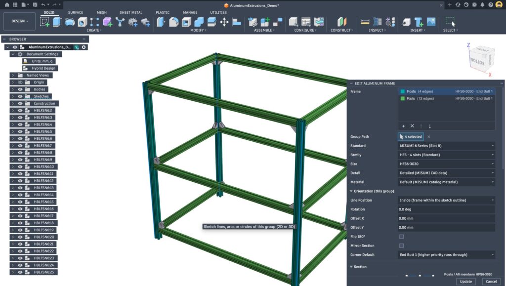
01 Draw the path
Sketch the frame skeleton as lines
02 Frames and hardware
Choose part numbers, create frames, add corner brackets
03 Export the order list
Part numbers, lengths and quantities in CSV / PDF
Cut list function (Aluminum Cut List)
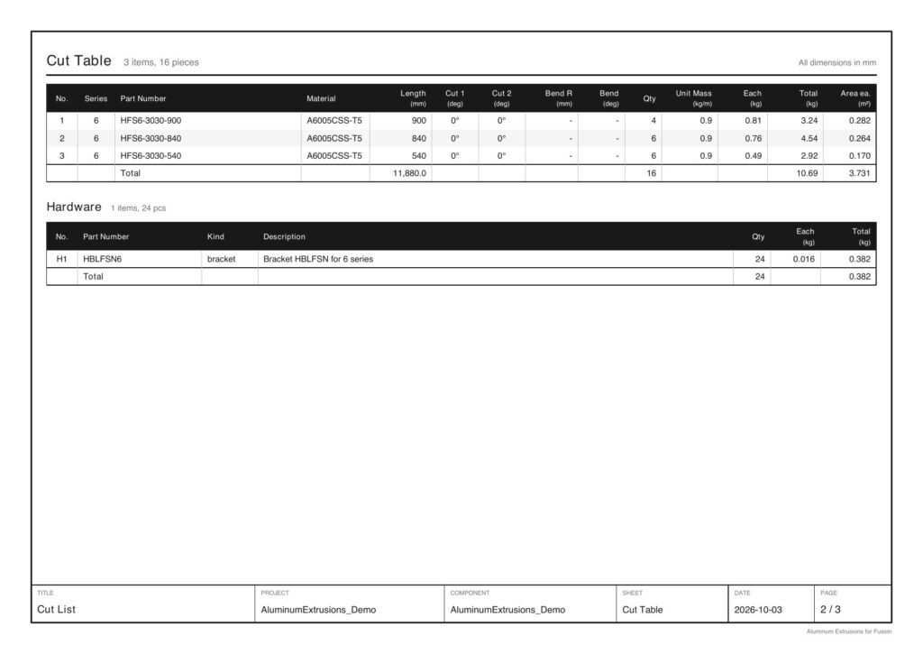
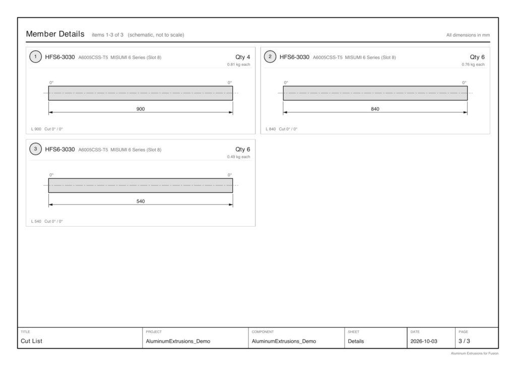
Automatically totals frames and hardware and exports an order list using MISUMI order codes as-is, a cut table, a hardware table and member detail drawings to CSV / PDF.
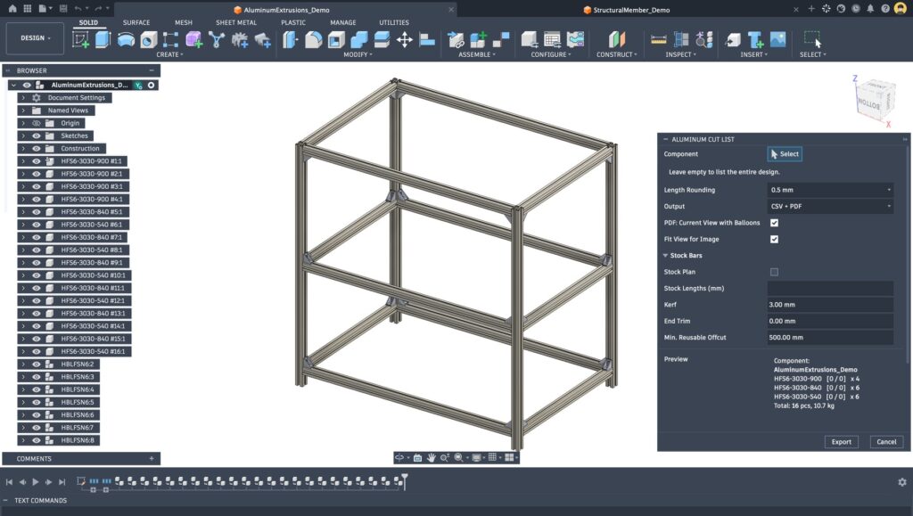
MISUMI order list
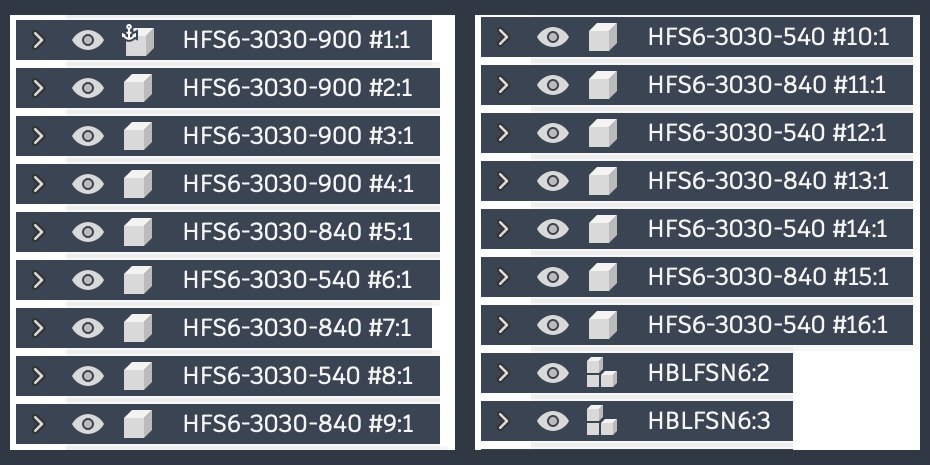
Order codes with length and quantities — e.g. “HFS6-3030-900 × 4” — at the top of the CSV, plus machining notes if there are cut angles.
Cut table and hardware table
Totals part number, length, cut angle, quantity and mass (catalog kg/m), plus quantities of placed brackets and nuts by part number.
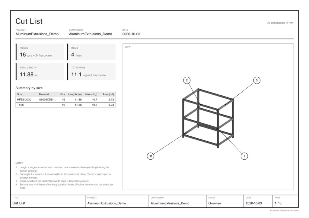
PDF report
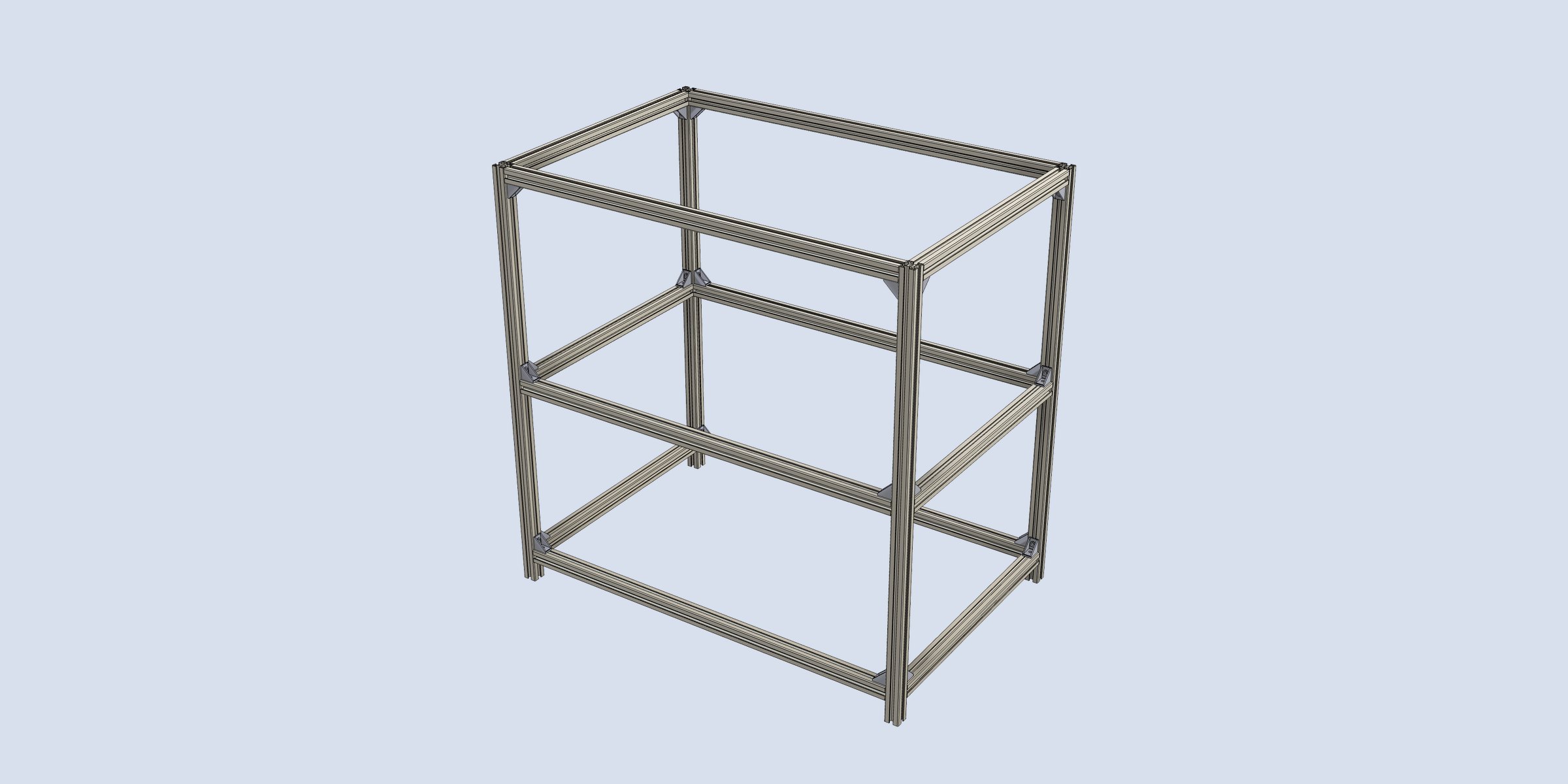
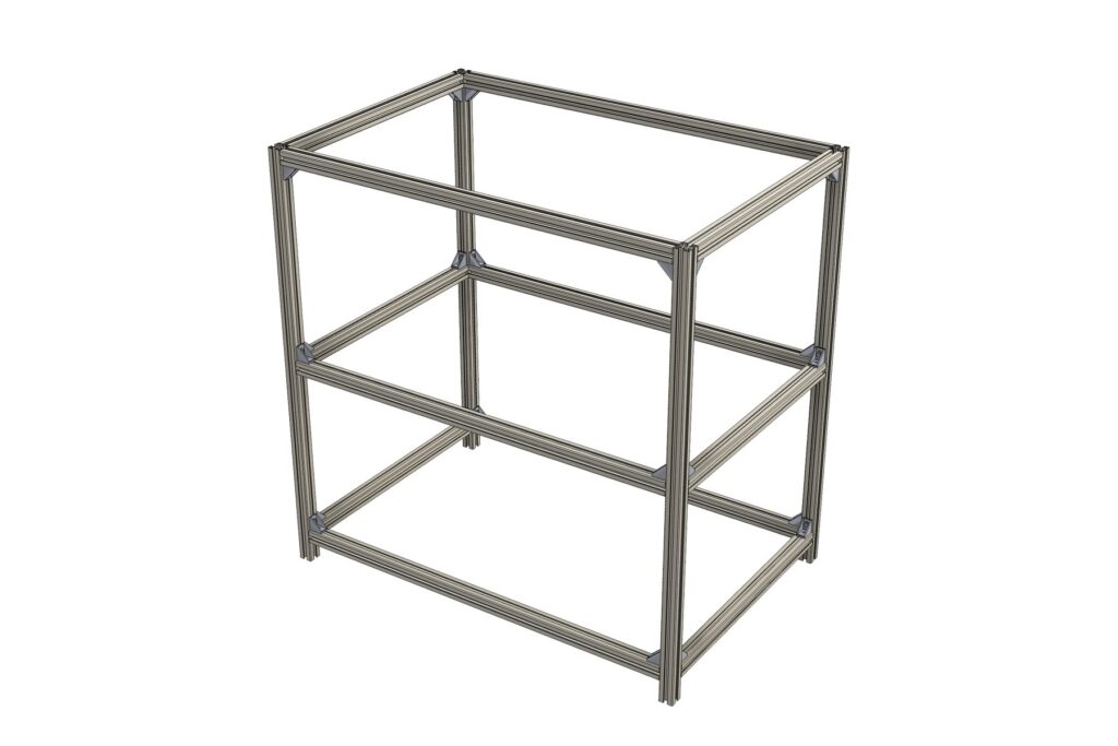
Exports an overall view with numbered balloons, cut table, hardware table and detail drawings of each member in a single PDF.
Example PDF output (overall view, cut and hardware tables, member detail drawings)
MISUMI Order List (top of the CSV)
| Part Number | Qty |
|---|---|
| HFS6-3030-900 | 4 |
| HFS6-3030-840 | 6 |
| HFS6-3030-540 | 6 |
| HBLFSN6 | 24 |
Specifications
| Supported series | MISUMI 5 (slot width 6) / 6 (slot width 8) / 8 (slot width 10) series |
| Hardware | Brackets HBLFSN / HBLFSNK / HBLFSNE, nuts HNTT / HNTF / HNTU / HNTP |
| Material | Aluminum 6061 / 6063, close to the catalog material, assigned automatically |
| Output | MISUMI Order List, Cut List, Hardware (CSV / PDF) |
| Requirements | Autodesk Fusion (Windows / macOS), Hybrid / Assembly Design |
Documents & contact
For adoption or demos, feel free to contact us. The product brochure (PDF) is also available.