
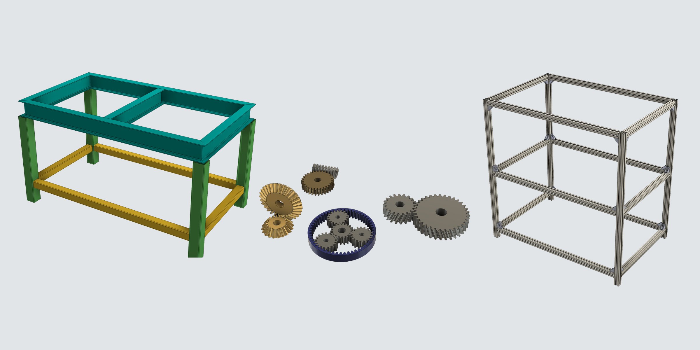
Steel frames, aluminum frames, gears. We turned the modeling that recurs in design work, and the cut lists and order lists that follow, into three add-ins for Autodesk Fusion. They are developed by Mikawa Industry’s MI Design Div.
Challenge
All of these were tasks designers repeated by hand.
- Steel frames: sketching and extruding members one by one and cutting joints by hand. Every dimension change meant starting over, and cut lists were picked off the drawings by a person.
- Aluminum frames: placing frames one by one, then copying lengths and part numbers into a spreadsheet to make the order. Every design change meant recounting lengths and brackets.
- Gears: searching for a manufacturer’s CAD data or settling for an approximate shape, and rebuilding it every time the tooth count or module changed.
Approach
We implemented them as commands added to Fusion’s Create panel. The geometry stays as a feature on the timeline, so it can be rebuilt later with different settings.
01
Structural Member
Assign JIS / ANSI steel sections to sketch lines to model frames and structures. Joints are trimmed automatically, and a cut list and a cutting plan for stock lengths are exported.
02
Aluminum Extrusions
Assign MISUMI aluminum extrusions to sketch lines to build a frame. Each member carries its order part number (with length), and brackets and nuts are placed as real geometry.
03
Gear Generator
Create gears by entering parameters. Tooth profiles are involute curves, and bores, keyways and mounting holes stay in a single feature.
Result
We released three products: Structural Member, Aluminum Extrusions and Gear Generator.
For steel sections and aluminum frames, cut lengths, cut angles and quantities can be exported as a cut list (CSV / PDF) and used directly for ordering material. Supported standards and part numbers are listed in Products.
Talk to us
We take requests for demos and inquiries about adoption.